
-
-
-
-
Contact

Products
Contact
Guangzhou Feihong Intelligent Technology Co., Ltd
Telephone:86 20 66606238 / 86 20 86920099
86 20 86920418 / 86 20 86920578
Fax: 86 20 86920126
Address: No. 118, Middle Section of Furong Avenue, Huadu District, Guangzhou City, Guangdong Province, China
Zip Code: 510860
E-mail:feihong@feihong-machine.com
Website:www.feihong-machine.com
")
FH135P-C
FH135P-C Technical Agreement (V400 Spindle)
Key words:
Technical Agreement
CNC machine tools
Five-axis milling and turning machining center
Seven-axis five-linkage CNC machine tools
11 axis cnc milling machine
Cnc vertical turning center
Rapid precision machining
Desk top cnc mill
Biggest milling machine
Micro cnc turning machine
Five-axis gantry machining center
Linear cnc turning machine
Biggest CNC milling machine
Cradle five-axis machining center
Five-axis vertical machining center
60P Vertical Five-Axis P-Type Machine
Category:
Product Description
Main configuration of 1. FH135P-C
| Serial Number | Configuration function and hardware description | Unit | Quantity | Remarks |
| 1. | FH host casting | Taiwan | 1 | |
| 2. | Siemens840DSL control system | Sleeve | 1 | |
| 3. | Display: 19LCD | Sleeve | 1 | |
| 4. | FH five-axis multi-function swing head (B-axis) | Sleeve | 1 | |
| 5. | Electric spindle of V400-A12 milling machine | Only | 1 | |
| 6. | X/Y/Z axis hollow cooling ball screw | Piece | 3 | |
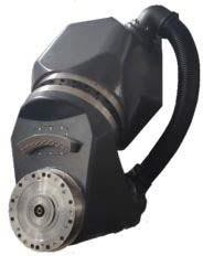
| 7. | Milling/turning direct drive turntable (C axis) | Sleeve | 1 | |
| 8. | B- axis RCN8380 29 bits absolute encoder | Only | 1 | |
| 9. | C- axis RCN2580 28 bits absolute encoder | Only | 1 | |
| 10. | BOSCH REXROTH Roller Linear Slide | Sleeve | 7 | |
| 11. | Temperature control device of electric box | Sleeve | 1 | |
| 12. | Spindle water cooling system | Sleeve | 1 | |
| 13. | Machine tool annular water spray | Sleeve | 1 | |
| 14. | Five axis head crescent spray water, crescent blow | Sleeve | 1 | |
| 15. | Front and side work door safety interlock systems | Sleeve | 1 | |
| 16. | Waterproof working compartment lighting lamp | Only | 2 | |
| 17. | Hydraulic station | Sleeve | 1 | |
| 18. | Central centralized feed lubrication device | Sleeve | 1 | |
| 19. | Operation side cleaning water gun and air gun | Sleeve | 1 | |
| 20. | cutting fluid system | Sleeve | 1 | |
| 21. | Fully enclosed protective sheet metal | Sleeve | 1 | |
| 22. | Operation box | Sleeve | 1 | |
| 23. | Electrical cabinet cooling unit | Sleeve | 1 | |
| 24. | Siemens electronic handwheel | Only | 1 | |
| 25. | Pedal spindle loose knife switch | Only | 1 | |
| 26. | Machine three-color lamp | Sleeve | 1 | |
| 27. | 40 HSK-A63 tool magazine and servo automatic tool change system | Sleeve | 1 | |
| 28. | X/Y/Z three axis absolute value grating ruler | Sleeve | 3 | |
| 29. | Spiral chip winding device and rear-row iron chip conveyor containing iron chip car | Sleeve | 1 | |
| 30. | Hexcon IRP25.50 infrared probe device | Sleeve | 1 | |
| 31. | Renishaw NC4F230 tool-set device | Sleeve | 1 | |
| 32. | Foundation horizontal cushion block and foundation bolt | Sleeve | 1 | |
| 33. | Technical Manual | Sleeve | 1 |
Basic specifications of 2. machine tools
| Specification/Model | Model | Unit | FH135P-C |
| Travel | |||
| X-axis travel | X axis travel | mm | 1450 |
| Y-axis travel | Y axis travel | mm | 1350 |
| Z-axis travel | Z axis travel | mm | 1100 |
| Spindle end face to work | Distance from spindle nose to work table surface | mm | 160-1260 |
| horizontal milling head | Horizontal milling head | mm | 30-1130 |
| Feed/Fast Moving Speed | Feed/fast moving speed | m/min | 40 |
| Feed force | Feed force | KN | 10 |
| Rotary table (C-axis) | |||
| Table size | Working table size | mm | Ø1400 |
| Maximum table load bearing | Max.table load (mill) | kg | 4000 |
| Max.table load (turning) | kg | 3000 | |
| Milling/turning table (milling and turning compound machining) | Milling/turning woking table(compound milling and turning) | rpm | 250 |
| Minimum Split Angle | ° | 0.001 | |
| Rated torque | Nm | 1330 | |
| Maximum torque | Nm | 2630 | |
| CNC swing milling head (B axis) | |||
| Swing range (0 = vertical/180 = horizontal) | Swing range(0=Vertical/180=Level) | ° | -15~180 |
| Fast moving speed and feed speed | Fast moving and feeding speed | rpm | 50 |
| Minimum Split Angle | ° | 0.001 | |
| Rated torque | Nm | 1050 | |
| Maximum torque | Nm | 2130 | |
| Spindle (milling) | |||
| Maximum spindle speed | Spindle speed | rpm | 12000 |
| Spindle power (S1/S6) | Spindle power | Kw | 48/71 |
| Spindle torque (S1/S6) | Spindle torque | Nm | 300/452 |
| spindle taper hole | Spindle tapre | HSKA100 | |
| Specification/Model | Model | Unit | FH135P-C |
| Tool magazine | |||
| Tool Interface | Tool interface | HSKA100 | |
| Tool magazine capacity | PCS | 40 | |
| Max. tool diameter/length/weight | Max.tool diameter/length/weight | Ø135/300/12 | |
| Tool change time (knife to knife) | Tool switch(Tool to) | S | 2 |
| Measuring device | |||
| infrared probe | Infrared probe | Hexcon IRP25.50 | |
| Tool measurement in machining area | Tool detection instrument in working processing area | Rensishaw NC4F230 | |
| Position accuracy (ISO230-2 and VDI3441) | |||
| X/Y/Z positioning accuracy | X/Y/Z positioning accuracy | mm | 0.008 |
| X/Y/Z repeat positioning accuracy | X/Y/Z Repeat positioning accuracy | mm | 0.005 |
| B/C positioning accuracy | B/C positioning accuracy | 10" | |
| B/C repeat positioning accuracy | B/C Repeat positioning accuracy | 4" | |
| Specification/Model | Model | Unit | FH135P-C |
| Controller | |||
| numerical control system | Control system | Siemens840D | |
| Other | |||
| Machine weight | Machine weight | Kg | |
Brief description of 3.
3.1 main machine technical specifications | Best rigid structure configuration

Design Features | Best Mechanics Line Casting Analysis Design
◆ Full box type thermal symmetrical casting structure, using Mihana grade high-grade cast iron
◆ Tempering and natural aging treatment to eliminate internal stress
◆ Structural natural frequency vibration eliminates material processing stress
◆ Full wall large area high rigidity column design, effectively improve the rigidity and static and dynamic accuracy
◆ Three-axis hollow cooling screw drive
3.2 electric spindle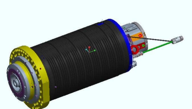
Design Features
According to the characteristics of their own machines, independent research and development production.
◆ HSK-A100 taper holes are used in FH135P-C models.
The use of external cooling system circulation cooling, effectively ensure the application of electric spindle.
3.3 CNC swing milling head (B axis)
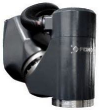
Design Features
◆ Independent design and production.
◆ Built-in DD motor zero transmission chain without backlash design.
◆ High acceleration characteristics.
The shortest spindle tool point and structural support point span, to achieve maximum cutting rigidity.
◆ Larger YRT bearings improve rigidity.
◆ Equipped with Heidelhain RCN8380 series absolute rotary encoder measurement system, full closed-loop control, to ensure the best accuracy.
◆ B- axis cooling system design to reduce heat transfer.
3.4 rotary table (C-axis table)
Design Features
◆ Independent design and production.
◆ Built-in DD motor zero transmission chain without backlash design.
◆ High acceleration and deceleration response characteristics.
◆ Larger YRT bearings improve rigidity.
◆ Large rated driving torque, positioning processing with worktable positioning and clamping device
◆ Meet the needs of milling, reduce the handling of parts, improve product accuracy.
◆ Equipped with Heidelhain high-precision rotary encoder measurement system, full closed-loop control, to ensure the best accuracy.
◆ Cooling system design to reduce heat transfer.
3.5 control system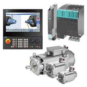
Selection characteristics
◆ Select the control host NCU730.3B for five-axis linkage (see the function table for detailed function configuration of the system)
◆ With RTCP function
◆ Select Siemens S120 driver with 3 times overload capacity and 1FT series motor with high motion characteristics
◆ Select TCU30.3 ICP427E as HMI interactive host, IPC has higher computing speed and higher storage space
3.6 automatic tool change system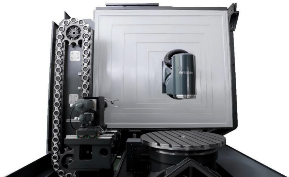
Design Features
◆ Independent design and production.
◆ Tool selection, tool change using servo motor control terminal action, more stable and more accurate.
Combined with the Siemens840DSL tool management function, more efficient tool management.
3.7 adjustable tool set
Design Features
◆ Equipped with Ransishaw NC4F230R knife-set instrument, higher precision.
◆ On-machine automatic tool setting, tool compensation automatically updated.
◆ The tool-pair device can be raised and lowered to save the space of the processing surface.
◆ Fully sealed sheet metal design protects the tool setting from water and iron scrap damage during processing.
3.8 infrared probe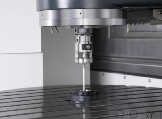
Design Features
◆ Equipped with Hexcon IRP25.50 trigger optical probe.
◆ In the machine workpiece to find and size detection, reduce manual detection error, improve product accuracy and processing efficiency.
◆ Save 90% on-machine auxiliary time.
3.9 safety protection sheet metal
3.10 appearance
The outer cover of the FH series five-axis machining center is designed to comply with strict CE safety standards to prevent operators from processing with full-tight sheet metal.
In addition to the warning nameplate, the operating door is also set up.
Safety switch to prevent accidents during operation or maintenance. And has a large peep window, convenient for the operator to understand the machine running processing
Situation.
3.11 cleaning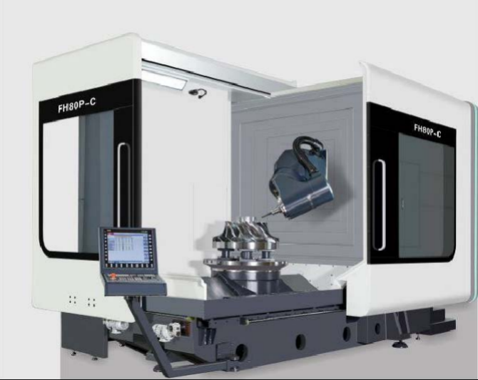
Use the telescopic shield and protective sheet metal to protect the chips generated during operation to avoid cutting splash and damage to other mechanisms
3.12 lighting
The working area is equipped with two LED lights, and the illumination of the lighting is maintained above 800LUX, which provides an appropriate bright working environment for the operator.
3.13 operability
The operating side is provided with a split sliding door to provide a large opening space, which is convenient for the workpiece to be loaded and unloaded from three directions freely using the crane.
Environmental standards and related requirements for the installation and use of 4. machine tools
4.1 environmental parameters
| Project | Environmental parameter conditions | Remarks |
| Temperature | 17 ℃ ~ 25 ℃ (during operation) | In order to keep the accuracy of the machine tool within the specified range, the best ambient temperature requires 17 ℃ ~ 25 ℃, and the temperature difference does not exceed ± 2 ℃/24h. The allowable range is 15 ℃ ~ 40 ℃, and the ideal operating environment temperature is ± 2 ℃. |
| 0 ℃ ~ 60 ℃ (during transportation) | ||
| Humidity | 40% ~ 70% at 20 ℃ | No condensation |
| Vibration | Below 0.5G |
4.2 installation site requirements
1) The equipment shall not be installed in radiation, such as microwave, ultraviolet, laser or X-ray range.
2) In order to ensure the machining accuracy of the machine tool and reduce the temperature difference around the equipment, please do not install it in the following areas:
◆ Direct sunlight
◆ High humidity
◆ Large temperature difference
◆ Vibration
◆ Strong magnetic field
◆ Dusty
3) Avoid the following situations around the installation area of the equipment:
◆ Garage
◆ Lane with frequent traffic
◆ Pressure or stamping equipment
◆ Electric welding, spot welding or hydrogen arc welding
◆ Substation
◆ High voltage line
◆ Dust-prone equipment or processing
4) The foundation of the equipment installation site needs to be designed and constructed in accordance with GB 50040-1996 "Code for Design of Power Machine Foundation.
5) The equipment installation site must have a fixed power supply that meets the relevant national requirements, and temporary power supply must not be used, and the equipment must be guaranteed to have good grounding protection. The machine tool shall have reliable grounding: the grounding conductor shall be copper conductor, the wire diameter shall not be less than 10mm2, and the grounding resistance shall be less than 4Ω.
6) Power interface: The power supply provided by the equipment installation site must be a three-phase four-wire system (U, V, W, N), and the power line voltage is AC380V. Attention should be paid to the voltage stabilization of the power supply, and the fluctuation of the power supply voltage must not exceed 5%. If the voltage is not stable in the area of use, the machine tool should be equipped with a CNC special regulated power supply to ensure the normal operation of the machine tool. The upper power switch of the equipment shall be D type 160A without leakage type.
7) The installation site of the equipment must have a stable air source, and a set of air source purification device (dehumidification, oil removal and filtration) should be added before the air intake of the machine tool.
8) compressed air interface: p = 4~6kgf/cm, q = 60 m/h, ¢ 10 quick connector is reserved at the air source interface, and ¢ 10 ~ m is reserved for temporary adjustment on site when the connector is connected to the equipment installation position. The main pipeline of compressed air must be equipped with main pipeline filter and dryer. The air pressure is required to be 0.5~0.7Mpa. Pressure dew point -20 ℃ to 0 ℃; oil content 1PPM; dust content <50μm.
9) Party A reserves enough installation space according to the machine tool appearance size of the equipment sample provided by Party B, so as to facilitate the positioning and maintenance of the machine tool.
5. equipment acceptance
a) Performance and configuration acceptance
1) Acceptance of technical performance of equipment by Party A:
◆ Appearance inspection
◆ Mechanical body standard specification acceptance
◆ No-load 24-hour operation
2) Party A checks and accepts according to the above configuration list
3) Acceptance of technical data by Party A
B) Accuracy index acceptance
1) Static accuracy detection
| Equipment model: FH135P-C | Name of equipment: Five-axis linkage milling lathe compound machining center | ||
| Factory No: | Factory Date: | ||
| Reference standards for testing items: GB/T34880.2-2017 and FH Feihong Factory Standard Allowance standard reference: FH Feihong Factory Standard Geometric accuracy test methods and conditions reference standard: GB-T 17421.1-1998 Positioning Accuracy Detection Methods and Conditions Reference Standard: VDI3441-1997 /ISO230-2:2006 | |||
| Serial Number | Test Items | Allowable Value | Detection value |
| 1. | Work surface level | a(Y axis direction):0.04/1000mm B (X axis direction): 0.04/1000mm | a: /1000mm b: /1000mm |
| 2. | Perpendicularity between X-axis motion and Z-axis motion | 0.01/300mm Must be marked: Left or Right | _____/300mm |
| 3. | Perpendicularity between Y-axis motion and Z-axis motion | 0.01/300mm | _____/300mm |
| 4. | Perpendicularity between X-axis motion and Y-axis motion | 0.01/300mm | _____/300mm |
| 5. | The degree of parallelism between the work surface and the X-axis motion. C- axis is detected at 0 ° | X≤ 500mm:0.010mm 500mm | _____mm |
| 6. | Parallelism between the work surface and the Y-axis motion. C- axis is detected at 0 ° | Y≤ 500mm:0.010mm 500mm | _____mm |
| 7. | C- axis 0 ° position reference parallelism of T-groove side and X-axis movement | 0.02/1000mm | _____/1000 mm |
| 8. | Periodic axial movement of the spindle | 0.01mm | |
| 9. | radial runout of spindle taper hole: a) Close to the end of the spindle; B) 200mm from the spindle end. | a) 0.004mm b) 0.010mm | a): _____mm b): _____mm |
| 10. | workbench center hole and working surface beating: a) Radial runout of center hole of workbench; B) Round runout of the working surface of the workbench. | a) 0.010mm b) 0.010/500mm | a): _____mm b): _____/500 mm |
| 11. | B axis at 0 ° spindle axis and Z axis Parallelism between movements: a) In the YZ vertical plane; B) In the XZ vertical plane. | a):0.010/300 mm b):0.010/300mm | a): _____/300mm b): _____/300mm |
| 12. | B- axis at 180 ° spindle axis and Y-axis Parallelism between line movements: a) In the ZY vertical plane; B) In the XY vertical plane. | a):0.010/300 mm b):0.010/300mm | a): _____/300mm b): _____/300mm |
| 13. | Verticality of spindle rotation axis and C- axis/bed surface in X direction when B- axis is at 0 ° | 0.010/300mm | _____/300mm |
| 14. | Verticality of spindle rotation axis and C- axis/bed surface in Y direction when B- axis is at 0 ° | 0.010/300mm | _____/300mm |
| 15. | X-axis positioning accuracy | 0.006mm | |
| 16. | X-axis repeat positioning accuracy | 0.004mm | |
| 17. | Y-axis positioning accuracy | 0.006mm | |
| 18. | Y-axis repeat positioning accuracy | 0.004mm | |
| 19. | Z-axis positioning accuracy | 0.006mm | |
| 20. | Z axis repeat positioning accuracy | 0.004mm | |
| 21. | B- axis positioning accuracy | 8 ″ | |
| 22. | Repeated positioning accuracy of axis B | 4 ″ | |
| 23. | C- axis positioning accuracy | 8 ″ | |
| 24. | C- axis repeat positioning accuracy | 4 ″ | |
2) The accuracy of test pieces, test standards and drawings shall be subject to the final technical agreement.
6. Quality Assurance
1) The quality assurance period is 12 months from the date of final acceptance and life-long service.
2) During the warranty period, Party B shall provide Party A with timely maintenance services and spare parts necessary for maintenance free of charge.
3) After the expiration of the warranty period, Party B shall still provide online services and technical guidance free of charge. offer to Party A at a preferential price
Timely supply of spare parts. When it is necessary to send someone to the site for maintenance, the corresponding fees shall be charged according to Party B's standards.

Welcome to leave a message
National Service Hotline
Guangzhou Feihong Intelligent Technology Co., Ltd.
Telephone 86 20 66606238 / 86 20 86920099 / 86 20 86920418 / 86 20 86920578
Domestic:13902405737 Manager Li
International:15013121816 Manager Wu
Fax: 86 20 86920126
Address: No. 118, Middle Section of Furong Avenue, Huadu District, Guangzhou City, Guangdong Province, China
Zip Code: 510860
E-mail:feihong@feihong-machine.com
Website:www.feihong-machine.com


Follow us
© 2022 Guangzhou Feihong Intelligent Technology Co., Ltd. SEO Tags Powered by www.300.cn City Product
WhatsApp: 15013026621
Domestic: 86-13902405737 Manager Li
International: 86-15013121816 Manager Wu
Add:fu Rong Road,Huadu District, Guangzhou City, China.
Email: feihong@feihong-machine.com
We will provide you with timely feedback